The tutorial below describes the aerial data processing without ground control points (GCPs) in the Agisoft Metashape Profession edition.
To evaluate accuracy and for more precise georeferencing, it is better to use markers. You can find an example of a workflow with ground control points in our article - Aerial data processing (with GCPs)
Processing of aerial images includes the following steps:
- Add Photos
- Align Photos
- Optimize based on measured camera locations
- Build Point Cloud
- Build DEM
- Build Orthomosaic
- Exporting the results
The data has been acquired using Wingtra platform (WingtraOne VTOL mapping drone) with Sony RX1RII camera, coordinates measured with a precise PPK method. No GCPs data was used for processing.
The dataset can be downloaded from the Wingtra website ("High-resolution quarry mapping" dataset): https://wingtra.com/mapping-drone-wingtraone/aerial-map-types/#3d-reconstructionAdd Photos
1. To add photos, select Add Photos... or Add Folder... command from the Workflow menu (Workflow > Add Photos... or Workflow > Add Folder...).
2. Then, browse the source folder and select files to be processed. In the Model window of the program, the positions of the cameras will be displayed during shooting.

Camera reference data can be loaded automatically from the EXIF file or importing file manually.
- In the first case: you need to select Import Reference from the EXIF button on the Reference pane.

Click the Yes button to import GPS data:

After that, the camera reference data will display on the Reference pane.

- In the second case, to import the camera coordinate data from the CSV file, click the Import Reference button on the Reference pane. Browse to the file containing recorded reference coordinates and click the Open button.

In the Import CSV dialog, set the parameters for import (coordinate system, delimiter, columns, etc.) Information on the accuracy of the source coordinates (x,y,z) as well as of the source orientation angles can be loaded with a CSV file as well. Check Load Accuracy option and indicate the number of the column where the accuracy for the data should be read from. It is possible to indicate the same accuracy column for all three coordinates/angles.

Additionally, it is possible to indicate accuracy data for the coordinates/orientation angles. Select Modify... command from the context menu of an image on the Reference pane and input accuracy data both for a position (i..e. x,y,z coordinates) and orientation data.

Align Photos
1. Select Align Photos... command from the Workflow menu (Workflow > Align Photos...).
2. Set the parameters in the Align Photos dialog window:
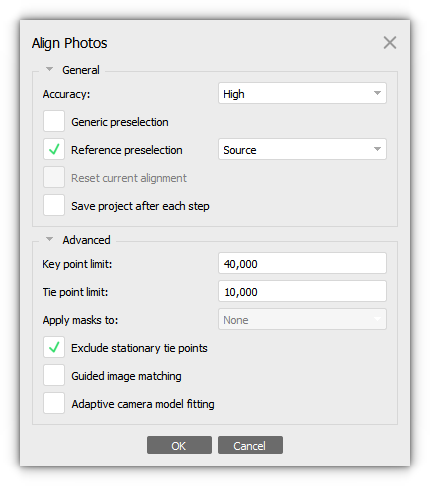
Please note: if you are using Source preselection, do not use it at the same time as Generic preselection.

If the coordinates of the images are not measured with centimeter accuracy, then we do not recommend using Source preselection. In the Source preselection mode the overlapping pairs of photos are selected based on the measured camera location.
More detailed description of all the parameters, please refer to our user manual - https://www.agisoft.com/downloads/user-manuals/
3. Click the OK button. The progress dialog box will appear displaying the current processing status. To cancel the processing, click the Cancel button.
4. Alignment having been completed, computed camera positions, and a tie point cloud will be displayed in the Model view.

Optimize based on measured camera locations
The optimization process usually improves the alignment results and reduces the errors, so it should be included in the common aerial data processing workflow.
1. Click the Optimize toolbar button on the Reference pane.
2. In the Optimize Camera Alignment dialog box, check additional camera parameters to be optimized.
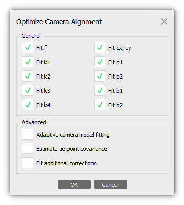
Adaptive camera model fitting - this option enables automatic selection of camera interior orientation parameters to be adjusted.

Estimate tie point covariance - the function allows to estimate the covariance values of the tie points.

Fit additional corrections option is reasonable if the current camera model cannot be accurately described with Brown's Model used in Metashape. Enabling this option may help achieve better accuracy for RTK/PPK datasets without ground control points (GCPs) utilization.
3. Click the OK button to start optimization.
Build Point Cloud
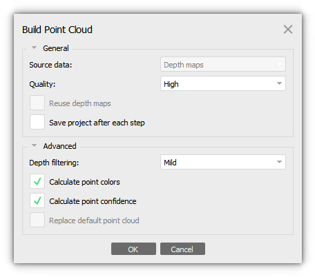
1. Select Build Point Cloud... command from the Workflow menu (Workflow > Build Point Cloud).
2. In the Build Point Cloud dialog box select the desired reconstruction parameters and click the OK button.
3. The progress dialog box will appear displaying the current processing status. To cancel the processing, click on the Cancel button.

Build DEM
1. Select the Build DEM... command from the Workflow menu (Workflow > Build DEM...).
DEM is calculated for the part of the model within the bounding box.
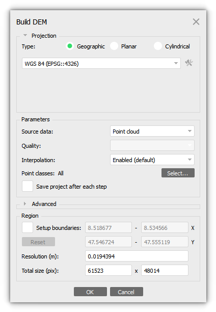
2. In the Build DEM dialog box, set parameters.
3. Click the OK button. The progress dialog box will appear displaying the current processing status. To cancel processing, click the Cancel button.

Build Orthomosaic
1. Select the Build Orthomosaic... command from the Workflow menu (Workflow > Build Orthomosaic...).
2. Set parameters in the Orthomosaic dialog window.
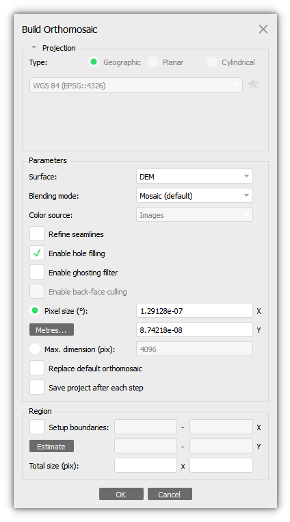
3. Click the OK button. The progress dialog box will appear displaying the current processing status. To cancel the processing, click the Cancel button.

Exporting the results
Export DEM
The following formats are supported for DEM export: GeoTIFF elevation data (*.tif); Arc/Info ASCII Grid (*.bil); XYZ file format (*.xyz); Sputnik KMZ (*.kmz); Google Map Tiles (*.zip); MBTiles (*.mbtiles); World Wind Tiles (*.zip); Tile Map Service Tiles (*.zip).
1. Select Export DEM... command from the File menu (File > Export DEM...).
2. In the Export DEM dialog, specify the desired coordinate system for DEM export. Check Write KML file and/or Write World file options to create files needed to georeference the orthomosaic in the Google Earth and/or a GIS-application, if necessary.
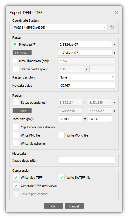
In Metashape it is possible to export DEM colored with the false colors (RGB) according to the height information. Select the Palette option in the Raster transform section of the Export DEM dialog box. The palette option is supported for the following export formats: TIFF, JPEG, JPEG2000, PNG.
3. Click the Export button to start the export.
4. Browse the destination folder, choose the file type, and print in the file name. Click the Save button.
5. The progress dialog box will appear displaying the current processing status. To cancel the processing, click the Cancel button.
Export Orthomosaic
The following formats are supported for orthomosaic export: TIFF/GeoTIFF (*.tiff); JPEG2000 (*.jp2); JPEG (*.jpg); PNG (*.png); BMP (*.bmp); Google Earth KMZ (*.zip); MBTiles (*.mbtiles); World Wind Tiles (*.zip); Tile Map Service Tiels (*.zip).
1. Select Export Orthomosaic... command from the File menu (File > Export Orthomosaic...).
2. In the Export Orthomosaic dialog box specify the coordinate system for the Orthomosaic to be saved in. Check to Write KML file and/or Write World file options to create files needed to georeference the orthomosaic in the Google Earth and/or a GIS, if necessary.
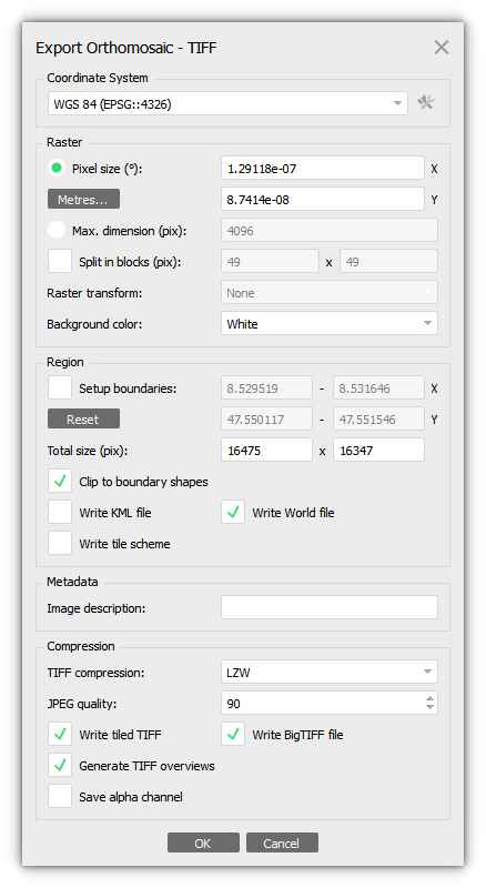
Please consider image formats limitations, when exporting large scale orthomosaic from Metashape Professional:
TIFF format doesn't allow to save files larger than 4GB.
JPEG format export is limited by 65535 pixels for any side of the image.
To avoid the format limitation issues you can:
- reduce the export resolution (m/pix) to fit the format limitations,
- use Split in blocks feature in the Export Orthomosaic dialog in order to export the orthomosaic in tiled blocks,
- use BigTIFF option for TIFF format export.
3. Click the Export... button to start the export.
4. Browse the destination folder, choose the file type, and print in the file name. Click the Save button.
5. The progress dialog box will appear displaying the current processing status. To cancel the processing, click the Cancel button.