Photos suitable for aerial data processing in Agisoft Metashape can be taken by any digital camera (both metric and consumer-grade), as long as you follow some specific capturing guidelines.
We recommend reading Image Capture Tips section which explains general principles of taking and selecting pictures that provide the most appropriate data for photogrammetric processing.
The tutorial below describes the main workflow processing steps and recommended parameters for aerial data processing in Agisoft Metashape Professional.
You can download an example of the data on our website - https://www.agisoft.com/downloads/sample-data/
Processing of aerial images with ground control points includes the following steps:
- Add Photos
- Interior and exterior orientation parameters
- GNSS/INS offset
- Align Photos
- Ground Control Points (Markers)
- Optimize Camera Alignment parameters
- Build Point Cloud
- Build DEM
- Build Orthomosaic
In order for calibration data and image coordinates to be automatically loaded to the project when adding images, please make sure that you have the appropriate options enabled in the Metashape Preferences dialog window. Select Tools > Preferences and open Advanced tab:

Add Photos
1. To add photos select Add Photos... command from the Workflow menu.
2. In the Add Photos dialog browse the source folder and select files to be processed. Click Open button.
3. Loaded photos will appear on the Workspace pane:

Interior and exterior orientation parameters
The camera position at the time of image capture is defined by the interior and exterior orientation parameters. Interior orientation parameters include camera focal length, coordinates of the image principal point and lens distortion coefficients.
Camera calibration
In most cases this is done automatically based on EXIF meta data. When EXIF meta data is not available, initial interior orientation parameters needs to be configured according to the camera certificate. Select Tools > Camera Calibration to check interior parameters.

It is important that information about pixel size and focal length is uploaded. It is important that these parameters are specified in mm.
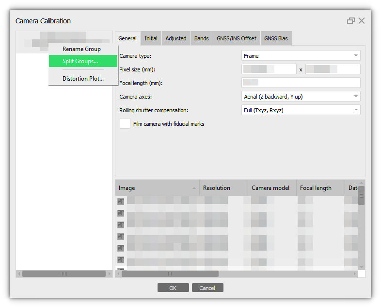
Please note that images taken from the same camera are automatically added to one calibration group. If you are processing several routes together, we recommend creating your own calibration group for each route. Select the corresponding images in the table in Camera Calibration and select the Create group command from the context menu:Also, if the images were divided into groups on the Workspace pane, you can divide the images based on these parameters. Select Split Groups option from the camera context menu:
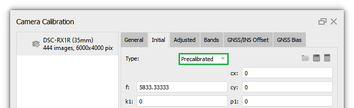
Also, if you know the camera calibration parameters, you can select Type - Precalibrated (Tools > Camera Calibration > Initial tab).
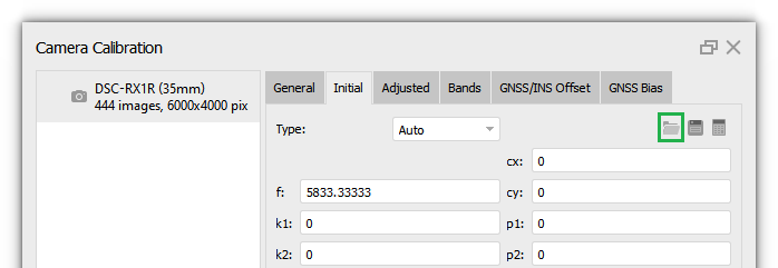
In our project, we used the Auto calibration type. At the alignment stage, the program will calculate the calibration parameters. The calculated parameters are displayed on the Adjusted tab. More information about camera calibration parameters you can find in our article - What does camera calibration results mean in Metashape?
If calibration parameters information is not saved in the image metadata, then the data can be imported from file, converted, or specified manually.
- Import precalibrated value from file:
In this case, the coordinates will be downloaded from the file. To do this, click the Load button in the Initial tab and select the desired calibration file:
Metashape supports the following formats: Agisoft Camera Calibration (*.xml), Australis Camera Parameters (*.txt), Australis v.7 Camera Parameters (*.txt), PhotoModeler Camera Calibration (*.ini), 3DM CalibCam Camera Parameters (*.txt), CalCam Camera Calibration (*.cal), Inpho Camera Calibration (*.txt), USGS Camera Calibration (*.txt), Pix4D Camera Calibration (*.cam)
OpenCV Camera Calibration (*.xml), Photomod Camera Calibration (*.x-cam), Z/I Distortion Grid (*.dat).
- Converted:
The calibration parameters can be converted if your calibration parameters are obtained in another application. Click Convert button:
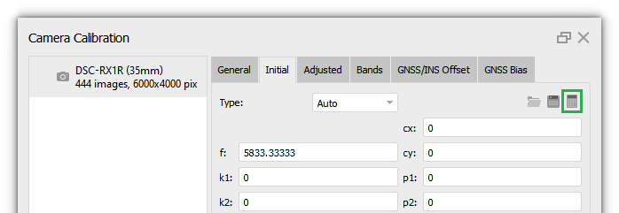
In the Convert Calibration dialog window select Type and specify calibration parameters or Import parameters from file:

To convert parameters click OK button.
- Specify parameters manually:
You can also specify the calibration parameters manually. Select Type - Precalibrated, then it is possible to enter values in the Initital tab, for example:
Import camera position
If you enabled the option to automatically upload coordinates in the Metashape Preferences dialog window before adding images to the project and the coordinates are saved in the metadata, they will be added automatically.
If the coordinates are saved in EXIF, but the option has not been enabled, then you can import the coordinates using the Import Reference from EXIF button on the Reference pane (to open Reference pane select View > Panes > Reference):

In our example, the coordinates for the images will be imported from a file:
1. Click Import button on the Reference pane. Browse to the file containing recorded reference coordinates and click Open button.

2. In the Import CSV dialog set the coordinate system, select the delimiter and indicate the column index for each coordinate. Indicate columns for the orientation data if present.

Optionally, indicate accuracy values for coordinates and rotation angles. If there is data about accuracy, then you also need to enable the Accuracy parameter and select the necessary columns.
3. Click OK button. The reference coordinates data will be loaded onto the Reference pane.

It is important to specify the accuracy with which the coordinates and angles were measured. Because by default, the program uses 10m and 10 deg:

Click Settings button on the Reference pane, and specify the Accuracy value:

Click OK button.
GNSS/INS offset
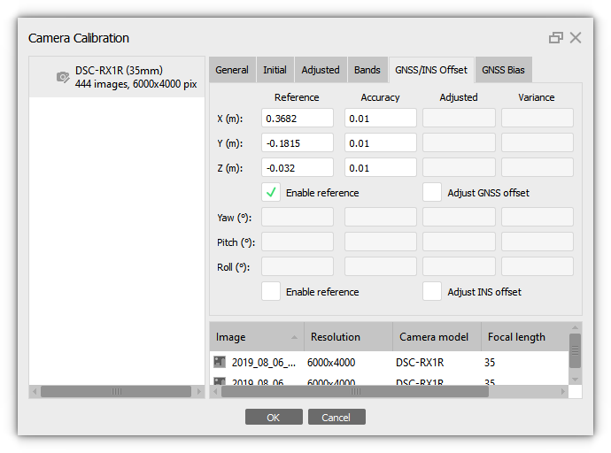
In case the coordinates input for the cameras are measured for the point where the measuring instrument is mounted (not the camera itself) it is also necessary to input measurement instrument shift with respect to the camera itself on GNSS/INS Offset tab of Camera Calibration dialog available from Tools menu.

If you have imported coordinates that have not been recalculated based on the correction for the offset of the GNSS INS receivers, it is important to specify these values manually.
Starting from Metashape 2.2.1, the ability to use GNSS and INS parameters separately has been added and adjusted.
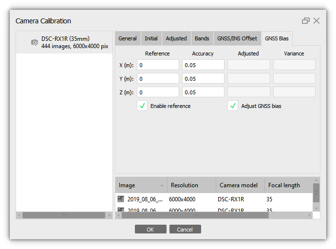
GNSS offset
Enable the Enable reference option in the Tools > Camera Calibration > GNSS/INS Offset tab and enter value for the GNSS offset manually:
It is also possible to refine these values by enabling the Adjust GNSS offset option:
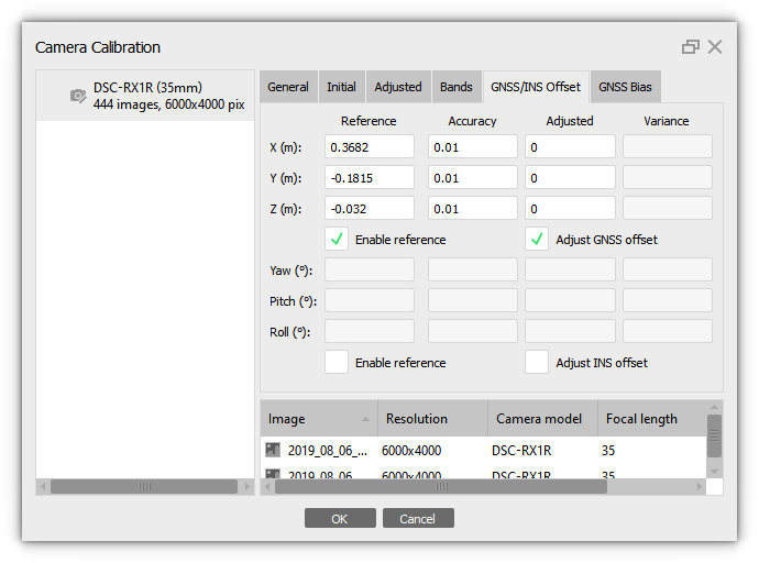
The offset of the GNSS receiver relative to the camera will be calculated. The offset is calculated relative to the camera, i.e. the offset of the GNSS receiver relative to the camera position will be calculated after align photos and optimization procedure.
INS offset
Rotation angles for the camera coordinates in Metashape are defined around the following axes: yaw axis runs from top to bottom, pitch axis runs from left to right wing of the drone, roll axis runs from tail to nose of the drone. Zero values of the rotation angle triple define the following camera position aboard: camera looks down to the ground, frames are taken in landscape orientation, and horizontal axis of the frame is perpendicular to the central (tail-nose) axis of the drone.
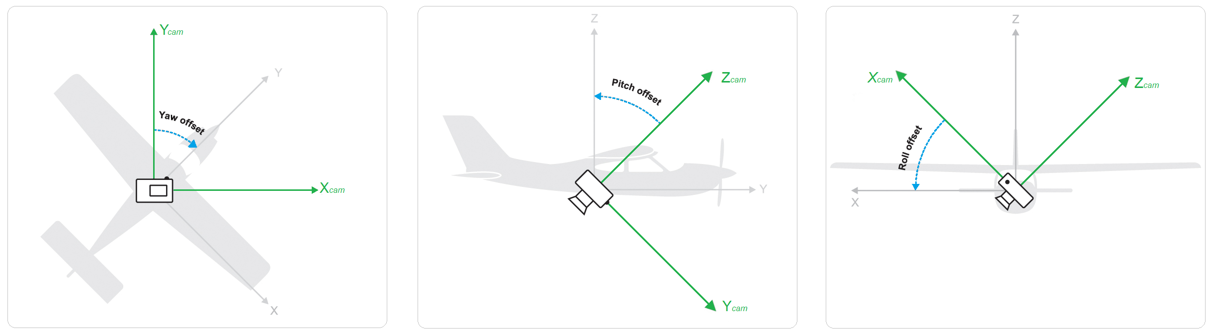
If the camera is fixed in a different position, respective yaw, pitch, roll values should be input on GNSS/INS Offset tab of Camera Calibration dialog. Turn on the Enable reference option for angles to specify INS offset. The signs of the angles are defined according to the right-hand rule. It is also possible to calibrate these values by enabling the Adjust INS offset option. There was no INS offset in our project, so we did not enter these values.
NOTE: it is important that if you do not know the offset for GNSS and INS data, but you would like to calibrate these parameters, then it is important that the project has control points, checkboxes for coordinates and/or angles are enabled, and it is important to set zero values as a first approximation.
Align Photos
Metashape estimates the camera position and orientation for each photo and generates a tie point cloud consisting of the tie points. The first step is called alignment. It includes aerial triangulation (AT) and bundle block adjustment (BBA). At this stage Metashape searches for feature points on the images and matches them across images into tie points. The program also finds the position of the camera for each image and refines camera calibration parameters (estimates interior (IO) and exterior (EO) camera orientation parameters). The results of these procedures are visualized in the form of a tie point cloud and a set of camera positions.
After you have verified that you have loaded the image data correctly, you can start image alignment.
If you want the coordinates of images and angles to be taken into account during alignment, it is important to enable checkboxes for coordinates and angles on the Reference pane.

1. Select Align Photos... command from the Workflow menu (Workflow > Align Photos...).
2. In the Align Photos dialog box select the desired alignment options. In most cases, it is sufficient to use the following parameters for alignment:

More detailed description of all the parameters, please refer to our user manual - https://www.agisoft.com/downloads/user-manuals/
If the coordinates of the images are not measured with centimeter accuracy, then we do not recommend using Source preselection. In the Source preselection mode the overlapping pairs of photos are selected based on the measured camera location.

If you are using Source preselection, do not use it at the same time as Generic preselection.

In the Generic preselection mode the overlapping pairs of photos are selected by matching photos using lower accuracy setting first.
3. Click OK button. The progress dialog box will appear displaying the current processing status. To cancel the processing click Cancel button. Alignment having been completed, computed camera positions and a tie point cloud will be displayed.

Ground Control Points (Markers)
Markers can be specified in one of the following ways:
- Imported from a separate text file (using character separated values format);
- Entered manually in the Reference pane.
1. Click Import toolbar button on the Reference pane. Browse to the file with Ground Control Points (GCPs) and coordinates, click the Open button.
2. In the Import CSV dialog set the coordinate system if the data present geographical coordinates. Select Delimiter and indicate the number of the data column for each coordinate.

If the file contains the coordinate accuracy value, then enable the Accuracy box for the coordinates and also specify the corresponding columns. In our example, this information is not stored in the file, we will specify the accuracy value manually.
4. Click OK button. And to create a marker you need to click Yes to All button:

The coordinates are imported into the project and will be displayed in the Reference pane. To enable the display of markers in Model view, click Show Markers button on the Toolbar button:

Markers are shown as blue flags in Model view.
If the coordinates for the markers were obtained with the same accuracy, then you can specify this value in the Reference Setting dialog window. Click Settings button on the Reference pane:

And specify the Marker accuracy value:

Starting from version 2.2.1, control and check points have different icons and will be displayed differently:

You need to enable or disable checkbox for markers on the Reference pane to change the type:
- If the checkbox is enabled, the point is the control point.
- When the checkbox is disabled, the point is the check point.
More information about how to work with markers in Metashape you can find in our article: Control and Check points for aerial surveys
When using GNSS during shooting, there may be a systematic shift between the coordinate system of the images and the coordinate system of the reference data (ground control points). The linear values of this shift can be calculated in Metashape. It is important that the project has GCPs and their positions are clarified on the photos. And it is also important to enable checkboxes for image coordinates on the Reference pane.

To minimize and calculate this error, enable the Adjust GNSS bias option on the GNSS Bias tab in the Camera Calibration dialog box (select Tools > Camera Calibration). Then, after alignment, the updated bias data will be available. If these offsets are known, it is also important to specify them. In this case enable checkbox for the Enable Reference option and specify the parameters.
Optimize Camera Alignment parameters
Metashape estimates internal and external orientation parameters during photo alignment. Possible non-linear deformations of the model can be removed by optimizing the estimated point cloud and camera parameters based on the known reference coordinates. During this optimization Metashape adjusts estimated point coordinates and camera parameters minimizing the sum of reprojection error and reference coordinate misalignment error.
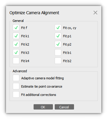
Adaptive camera model fitting - this option enables automatic selection of camera interior orientation parameters to be adjusted.

Estimate tie point covariance - the function allows to estimate the covariance values of the tie points.

Fit additional corrections - with this option enabled Metashape estimates additional coefficients that are necessary to achieve better accuracy. There are different corrections that allow to compensate the distortions that cannot be described by the Brown's model.
Build Point Cloud
Select the Build Point Cloud... command from the Workflow menu (Workflow > Build Point Cloud...). In the Build Point Cloud dialog box select the desired reconstruction parameters.
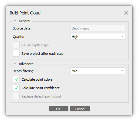
You can enable calculate point confidence parameter, which represents the number of depth maps used for the given point generation.

Confidence value can be used to perform additional filtering of low confidence points. You can find more information about confidence in our article: Point cloud editing with confidence filter tool
Click OK button when done. The progress dialog box will appear displaying the current processing status. To cancel processing click Cancel button.

If you want to build a DTM, then you need to classify the point cloud. You can find examples of working with classification and DTM construction in our articles:
Point Cloud Classification
Aerial data processing(SenseFly eBee)
Build DEM
Metashape allows to generate and visualize a digital elevation model (DEM). A DEM represents a surface model as a regular grid of height values. DEM can be rasterized from a tie point cloud, point cloud, depth maps, laser scans, mesh and tiled model, Point cloud + Laser scans.
Build DEM procedure can be performed only for projects saved in .PSX format. DEM can be calculated for referenced or scaled projects only.
Select the Build DEM... command from the Workflow menu (Workflow > Build DEM...). In the Build DEM dialog box set Coordinate system for the DEM or choose the projection type. Select source data for DEM rasterization.

Click OK button when done. The progress dialog box will appear displaying the current processing status. To cancel processing click Cancel button.

You can find some information about DEM in our solutions:
DEM Generation
DEM based measurements
DEM editing tools
You can generate contours after you build DEM. Select Tools > Generate Contours. In the Generate Contours dialog select DEM as the source data for calculation. Set values for Minimal altitude, Maximal altitude parameters as well as the Interval for the contours. All the values should be indicated in meters.

Click OK button. When the procedure is finished, a shape layer with "contours" label will be added to the project file structure shown on the Workspace pane. To display them in the Ortho view, you need to enable the Show Shapes button on the Toolbar:

You can manually edit сontours (for example, around trees) using the selection tools and delete the shape you don't need:

Contour lines can be exported using Export Contours command from the contour lines label context menu on the Workspace pane. Alternatively the command is available from the File menu. In the Export Contour Lines dialog it is necessary to select the type of the contour lines to be exported. A shape file can store the lines of the same type only: either polygons or polylines
Build Orthomosaic
Orthomosaic is obtained by orthorectification of the original images. Metashape enables to perform orthomosaic Seamline editing for better visual results. You can read more information about Seamline editing in our solution.
Please note that the quality of orthomosaic depends on the quality of the alignment of the source data and the surface on which you use to build the orthomosaic.
Select the Build Orthomosaic... command from the Workflow menu (Workflow > Build Orthomosaic...). In the Build Orthomosaic dialog box set Coordinate system for the Orthomosaic referencing of the select projection type. Select the type of Surface data that will be used to build the orthomosaic:
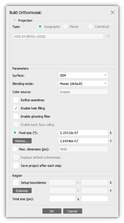
More detailed description of all the parameters, please refer to our user manual - https://www.agisoft.com/downloads/user-manuals/
Important! When using a Point cloud or Laser Scans as a Surface, the points will be used not only as a surface, but will also be projected onto a plane. That is, as a result, orthomosaic will be built not from images, but from a point cloud.
Click OK button when done. The progress dialog box will appear displaying the current processing status. To cancel processing click Cancel button.

After building orthomosaic, you can perform vectorization of your data using vectorization tools - Vectorization tools.

It is also possible to manually edit the orthomosaic - Orthomosaic seamline editing (patching)