Coded targets are printed markers that can be placed in the scene before photos are taken and could be used in Agisoft Metashape as reference points for coordinate system and scale definition or as a valid match between images to help camera alignment procedure via Align Selected Cameras option.
Markers and scale bars are available only for work in Metashape Pro version.
The article describes the following steps:
- How to Print Coded Targets
- How to Place Coded Targets in Scene and Take Photos
- How to Detect Coded Targets Automatically
- How to Create Scale Bar and Set Up Reference Distance
Sample data can be downloaded for practice purposes.
How to print coded targets
1. Select Tools Menu > Markers > Print Markers... command. The selected parameters will be used for PDF file generation in the Print Markers dialog.

2. Click OK and in the opened Save As dialog specify the folder for PDF file to be saved in.
3. Exported PDF file will contain all the possible coded targets for the selected type, so it is not necessary to print all the pages.
4. Select a few pages (depending on the number of targets to be placed) from the middle of the document and send them to the printer.

How to place coded targets in the scene and take a photo
When planning a shooting session with encoded tags, it is important to consider the following points:
- Coded targets should be flat, any deformations should be avoided.
- Coded targets should be circles with black and white segments (or with the inverted colors), so you have to cut them keeping in mind circle dimensions and additional outer buffer - about 1/3 of the outer circle radius.

- Any changes in the coded target pattern must be avoided.

- Once the coded targets are printed, place them in the scene or around the object of interest so that they could be clearly seen from at least of a couple of images.

Please note that the size of the coded targets should not be too big or too small compared to the object or scene. It is recommended that the radius of the central black circle-point on the taken photo is not greater than 30 pix. At the same time, the minimal radius of the central solid circle should be about 4-5 pixels.
Agisoft Metashape supports four types of circular coded targets (CTs): 12 bit, 14 bit, 16 bit and 20 bit. While 12 bit pattern is considered to be decoded more precisely, whereas 14 bit, 16 bit and 20 bit patterns allow for a greater number of CTs to be used within the same project.
How to Detect Coded Targets Automatically
1. Select Tools > Markers > Detect Markers... command.

2. In the Detect Markers dialog choose the corresponding Marker Type and adjust Tolerance value.
3. Click OK and wait until the marker detection procedure is finished. Detected markers will be named correspondingly to the coded targets labels.

How to Create Scale Bar and Set Up Reference Distance
Providing that before or after the shooting session some of the linear distances between the coded targets have been measured, it is possible to set up the scale of the model using this information. Actually, coded targets detection could be performed even after the model has been processed.
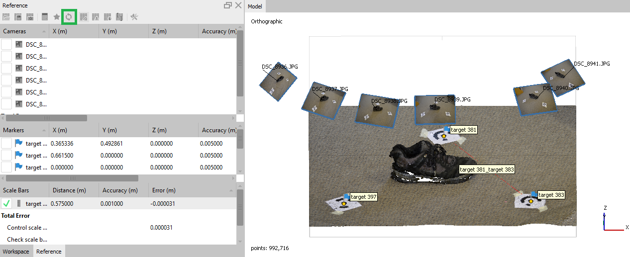
1. If the camera position has not been estimated yet, proceed to Align Photos procedure (Workflow > Align Photos...). Once the photos are aligned you can see the markers in the Model view:

2. To create a scale bar consequently left-click on the markers in the Model view (with any selection tool active, while holding the Ctrl key), that corresponds to the scale bar ends. Then right-click in the model view or on the pair of selected markers in the Workspace pane to open the context menu and select Create Scale Bar option.

3. Repeat for every pair of markers with know distance between them.
4. Go to the Reference pane and insert the distance for every scale bar the distance is known for.
Values can be entered if the Source tab is open, please check the corresponding View Source button on the Reference pane:

5. Check all the scale bars you want to use for model scaling and press Update button on the Reference pane toolbar. The scale will be applied to the model.
If you need to apply correct model orientation in the space, then we can offer try to use Rotate Object tool on the Toolbar:
